
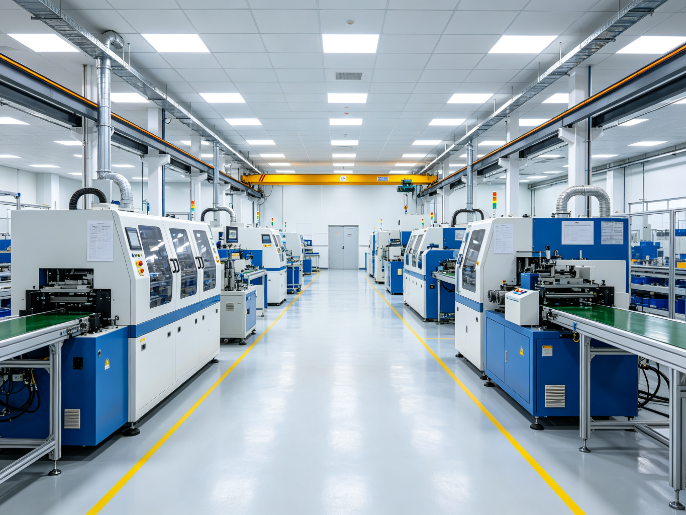
TL;DR. A palletizing cell looks simple from the aisle: a robot standing beside a conveyor, picking cases and stacking them on a pallet. The part that decides whether the cell fits the room, keeps the line pace, and lets a finished pallet be exchanged without stopping production is the layout drawn before the robot order is placed. This guide breaks the palletizer cell layout down for 2026 buyers: robot reach and payload sweet spot for common case and pallet sizes; the floor footprint a finished layer and a stacked load actually require; the guarding zone around the arm; the infeed-to-discharge flow direction; single-station versus side-by-side dual-station arrangement; and floor loading, aisles and service drops. Price bands below are typical ex-works planning ranges, before installation, controls, freight, tooling and civil work. A cobot palletizing cell typically sits in the low five figures to mid five figures, a compact 4-axis articulated cell in the mid five figures to low six figures, a high-duty dual-station robotic cell in the low to mid six figures, and a conventional gantry or column layer palletizer in the mid to high six figures. Cycle planning runs roughly 4 to 8 cases per minute on cobot cells, 8 to 15 on compact 4-axis units, 12 to 25 on high-duty articulated cells, and 15 to 30 plus on conventional layer palletizers; treat these as planning bands on regular cases, not guaranteed cycle times. Gripper and end-of-arm selection, teach-pendant versus offline programming, fence material choice, upstream accumulation buffering and conveyor type are covered in our existing buying guides and are only referenced here, not repeated.
By Kevin Zhou, Field Application Engineer — End-of-Line Cell Layout and Integration. Kevin has spent 11 years laying out, commissioning and troubleshooting robotic and conventional palletizing cells across CPG, food, building-material and logistics plants, and has reviewed reach, footprint, guarding and flow arrangement on more than 120 palletizing installations.
What the cell layout actually decides
A palletizing cell is a small production zone assembled from an infeed conveyor, a robot or palletizer head, one or more pallet positions, a discharge conveyor or pallet pickup point, guarding, access gates and the services that feed the machine. The layout places those elements in relation to one another and to the line beside it. It sets the radius the arm has to reach, the square meters the cell consumes, where people and forklifts can walk, how a full pallet leaves the cell, and how an empty one gets in.
Layout decisions are shared across three parties in the plant. Production cares about throughput and product mix: how many cases per minute the cell holds, and how the cell absorbs changeovers. Maintenance cares about access: can a technician reach the robot base, the gripper and the guard gate without crawling under a conveyor, and where are the wear parts? Environment, health and safety cares about separation: where the arm can move, who can enter the zone, and how the machine stops when someone does. A layout drawn by one party alone usually disappoints the other two after commissioning.
We see this on the floor when a cell is ordered on robot brochure specs before the floor plan is fixed. The reach turns out to be short for the top layer at the far pallet corner. The pallet exchange spot blocks the forklift aisle. The discharge conveyor crosses the same path as finished-goods traffic. The finished pallet waits beside the cell because there is no room to turn it toward the stretch wrapper. Each of these problems traces to a layout choice, and each costs more to fix after the concrete, guarding and conveyor are in place than it would have cost to specify correctly at the start.
The sequence below runs from product facts to floor facts, and it matches the order a competent layout review should follow. First, fix the product and pallet specs: case dimensions and weight, cases per layer, layer pattern, pallet footprint, finished stack height. Second, derive the reach and payload class those specs demand. Third, choose the station count and arrangement. Fourth, set the infeed-to-discharge flow. Fifth, draw the guarding envelope around the working envelope. Sixth, check floor loading, aisles and service drops. Sections below walk through each step.
Reach and payload: the sweet spot that sets the cell radius
Reach and payload are the two robot specs that decide where the base can stand and how many pallet positions the cell can hold. Brochure figures usually quote a maximum working radius and a headline payload at the wrist, but the planning numbers you need are narrower: the rated reach at full payload, and the effective payload after the gripper and layer are counted.
Reach on an articulated robot is a radius measured from the base axis. The arm sweeps that radius on a plane, but a pallet layer sits at some height above the floor, and the top layer of a tall stack sits near the machine’s vertical limit. The worst-case point is the far corner of the pallet at the top layer, not the center of a bottom-layer case near the base. If the base is placed to cover the infeed conveyor and two pallet positions, every corner of every layer has to stay inside the rated reach, with a small margin left for pattern changes and pallet placement variation. A robot sized to the average case position will look fine in the demo and fight the far corners in production.
Payload math starts with the gripper, not the case. The wrist carries the gripper or end-of-arm tool, the case or cases held in that cycle, and any vacuum or finger hardware hanging below. A typical vacuum gripper for cartons can weigh 40 to 80 kg; a clamp or bag gripper more. Add gripper weight to the held-case weight, then add a safety margin commonly in the 20 to 30 percent range, and that sum is the class the robot should be ordered in. Wrist torque and moment matter as much as headline payload for tall, wide layers: a heavy gripper held out at arm’s length loads the wrist joints even when the case itself is light. The case, bag or tray surface and the gripper type that match it are detailed in our robotic palletizer gripper buying guide; this section stays on how the gripper weight feeds back into reach and cell radius.
The sweet spot for common applications falls into planning bands rather than one universal machine. Standard cartons on GMA or EPAL pallets, with cases in the 10 to 25 kg range, are usually covered by a 4-axis machine in the 120 to 200 kg payload class and a 2.0 to 2.6 m reach, standing between two pallet positions. Heavy bags, buckets or bulky cases in the 25 to 50 kg range lean toward a 6-axis machine in the 250 to 500 kg class with 2.2 to 3.2 m reach. Finished stacks above about 2.0 m need the vertical reach checked against the top-layer height, and oversized 1200 by 1200 mm pallets or two-layer picks need the far-corner reach drawn out on a scale plan before the base location is fixed.
There are costs to leaving the sweet spot in both directions. A robot sized too small overreaches: the arm runs at the edge of its radius, cycle time slows, the wrist works near its torque limit, and corner cases land with visible placement error. A robot sized oversized for the load raises purchase price, consumes more floor around the base, and often carries more payload and reach than the line will ever use. Match the class to the worst-case load and the farthest corner, then leave margin; do not match it to the largest case the plant has ever shipped.
A worked example helps. A line runs 20 kg cartons, four cases per layer, with a 60 kg vacuum gripper. The effective wrist load is 60 plus 20, or 80 kg per pick, and a 120 to 180 kg class robot covers that with margin. If the same gripper handles a future 35 kg bulk case, the load moves to 95 kg and the class should be reviewed before that SKU lands. Reach in this example has to cover the infeed pickup, both pallet footprints and the top layer at roughly 1.8 to 2.0 m stack height; drawing those points on a layout shows whether a 2.0 m reach base can sit between the two positions or whether a 2.4 m machine and a wider cell are needed.
Layer pattern footprint: case size, pallet footprint and stack height
The layer pattern defines the horizontal area the robot must reach on each pallet. Regular cartons stack in rows and columns with an interlocked or columnar pattern; cases per layer come from the pallet footprint divided by case dimensions, minus any allowances for overhang and pattern gaps. Bags, trays, bundles and mixed-orientation packs do not form neat grids, and their footprint envelope is wider than the neatest arrangement suggests. The layout should be checked against the largest case in the range and the loosest pattern the line runs, not the neatest demo pattern.
Pallet dimensions vary by region and duty. Common North American GMA blocks run about 1219 by 1016 mm; European EPAL and EUR blocks run 1200 by 800 mm or 1200 by 1000 mm; industrial and building-material pallets run up to 1200 by 1200 mm or larger. Each pallet footprint sets a corner distance from the base. A robot that covers a 1200 by 800 mm block between two positions may not cover a 1200 by 1200 mm load in the same spot, and an oversized pallet also changes the discharge aisle and the wrapper opening downstream.
Stack height sets the vertical reach and the discharge envelope. Finished loads commonly run 1.5 to 2.2 m high, including the pallet; bulky products and building materials stack higher. The robot has to place the top layer at that height without the arm folding over the racking or the guard fence. The discharge conveyor or pallet pickup point has to clear the same height, and the area above the empty-pallet drop needs room for a stack of empties to be delivered or exchanged. Pattern changes between SKUs, and the teach or offline setup that stores those patterns, are covered in our robotic palletizer programming buying guide; here the pattern matters only for the footprint and reach it imposes on the layout.
Overhang and load stability belong in the layout check too. Cases that overhang the pallet edge by more than a small allowance do not build a stable stack, and a pattern that looks fine on paper can push cases past the pallet corner once the robot places them with repeatability error. Mixed-SKU layers that combine different case depths need the widest combined footprint drawn out, because that widest arrangement sets the reach and guarding distance even if it appears on only one SKU per shift.
Guarding zone around the robot
Note: guarding material choices — wire mesh, polycarbonate, light curtains and scanners — are compared in our end-of-line safety fence buying guide. This section covers the layout-level decisions the zone imposes: where the fence line sits, how access gates arrange, and what clearance the working envelope needs around it.
Industrial robot cells are integrated systems governed by safety requirements for robot applications and cells, reviewed through a machinery risk assessment that identifies hazards along the robot’s path, at the infeed and discharge, and during pallet exchange. The fenced or sensed zone must separate operators from the arm’s working envelope. The fence line does not sit tight to the envelope: standards and risk assessments allow for reaching over or under a barrier, and for maintenance movement inside, so the perimeter sits at a calculated distance beyond the maximum reach, with gate interlocks, e-stop positions and presence-sensing devices where people cross the infeed or discharge.
The zone dimension follows a simple rule of thumb for planning: the robot working radius plus a reach-over or reach-under margin, plus a maintenance clearance between the arm envelope and the fence, plus the thickness of the fence structure itself. A high-duty articulated cell typically adds 0.8 to 1.5 m of perimeter clearance beyond the arm envelope on each side, depending on barrier height and access arrangement. Drawing the fence tight to the envelope saves a square meter or two on paper and removes the space a technician needs to service the wrist, gripper and base.
Access arrangement splits into functional gates rather than one big door. A pallet exchange gate or opening lets full pallets leave and empty pallets enter; a maintenance door gives service access to the robot and guard hardware; the infeed and discharge sides may use light curtains, scanners or interlocked conveyor gates instead of solid fence where product flows through. Each gate needs its own interlock, reset point and e-stop position in the layout. Where operators manually present or remove product, the sensed opening and the stopping distance of the arm are checked together; a fence that looks adequate from the outside can still leave a reach-over path along the top or under the bottom rail.
Two layout errors show up repeatedly. The first puts the maintenance door where the full-pallet discharge also runs, so service access and forklift traffic share one opening. The second places a gate on the line side where operators walk daily, turning a safety interlock into a nuisance that gets bypassed. Plan gates around who crosses the zone and why: pallet exchange traffic, service access, product flow, and emergency egress each have a separate position in the layout.
Infeed-to-discharge flow direction
Flow direction fixes how product arrives at the robot and how the finished load leaves, and it decides the cell’s relationship to the upstream and downstream line. The three common arrangements are a straight-through flow, an L-shaped flow and a U-shaped flow, with the robot standing beside or between the conveyors.
In a straight-through layout, the infeed conveyor runs past the robot in one direction and the discharge continues along the same axis; the robot sits to one side and the pallet positions occupy the other side or the corner. This suits a long production line where the palletizer drops in at the end, and it keeps conveyor runs simple. In an L-shaped layout, product turns 90 degrees between infeed and discharge; the robot sits at the corner, and pallet positions fit on the two free sides. In a U-shaped layout, infeed and discharge run parallel on the same side of the cell, bringing product around the robot; this compresses floor length but needs care to keep the two conveyors and their traffic from crossing.
The infeed side carries accumulation before the robot. A short surge table lets the cell absorb short gaps and bursts in case flow without the robot waiting on a slow conveyor; choosing belt, live-roller or rotary accumulation is covered in our end-of-line accumulation table buying guide. The conveyor that feeds the robot needs singulation, spacing and orientation that match the gripper and pattern; if cases arrive overlapping or twisted, the cell spends its cycle correcting the feed instead of stacking. Belt, roller and modular plastic conveyor selection for the infeed and outfeed is covered in our conveyor system buying guide; the layout question here is where each conveyor enters and leaves the perimeter, and what clearance the transfer points need.
The discharge side carries the finished pallet toward stretch wrapping, strapping or shipping. The layout has to leave room for the load to leave the cell at the finished stack height, turn or transfer onto a discharge roller or chain conveyor, and meet the wrapper or strapper opening without a manual lift. If forklifts remove pallets directly, the pickup spot must sit in the forklift aisle with room for the truck to enter, turn and back out. A discharge that crosses the main pedestrian aisle or the inbound raw-material path creates a conflict that operators route around informally.
Flow direction also accounts for future change. A cell added today at the end of one line may later share a line that extends, gains an upstream machine, or changes product size. Keeping the discharge side and the pallet exchange side open to the aisle, rather than tight against a wall or a column, leaves room to extend the conveyor or add a second station. The line geometry in the plant — where the case sealer, packer and wrapping machines sit, where columns and drains fall, where doors open — should be overlaid on the cell plan before the flow direction is locked.
Single line versus side-by-side dual station
The station count decides how pallet exchange fits into the cycle. A single-station cell holds one pallet position at a time. When the load reaches the target height, the robot stops placing cases, a full pallet is removed by forklift or conveyor, an empty pallet is presented and squared, and the robot resumes. That exchange window is dead time in the cycle; on a single station it repeats every load, and the operator or truck has to be ready when the stack finishes.
A dual-station cell holds two pallet positions, side by side or opposing one another, and the robot alternates between them. While one load is completed and exchanged, the robot stacks on the other position, so exchange happens in parallel with production rather than after it. The footprint grows by the second pallet position plus guarding around it, and the reach has to cover both positions from the base, but the cell keeps running through the exchange. This is the standard arrangement at mid and high volume, where a stopped robot waiting on a pallet truck shows up directly in output.
Station layout options beyond the basic pair include an empty-pallet dispenser that feeds stacks of pallets automatically, a slip-sheet or sheet dispenser between layers where product needs separation, and a pallet changer or third position for high-volume lines where even two positions create exchange pressure. Empty-pallet handling adds its own floor area beside the cell: the dispenser stack, the pallet entry path, and clearance for the pallet to be lifted and placed on the position.
The choice between single and dual station follows volume and labor, not preference. A low-volume line with an operator nearby and a short exchange cycle can run a single station and save the second position’s floor and price. A multi-shift line running a steady case rate should compare the exchange downtime per load against the added footprint and cost of the second station; where the line pace would otherwise stop every finished load, dual station pays back in recovered output. A third position or automatic dispenser is usually justified only where exchange time, labor or stack weight makes a two-position layout slow the cell.
Floor loading, aisles and service drops
Floor loading is the layout check that most often surfaces only after the equipment arrives. The robot base carries the machine weight and reaction forces; each pallet position carries the pallet, the finished stack and any handling force, with finished loads commonly in the 1000 to 1500 kg range and heavier for building materials or bulk bags. A ground-floor slab in a standard plant usually accommodates these loads, but older slabs, lightweight industrial floors, raised platforms and mezzanines need a structural check before the cell is drawn on them. A second-floor or mezzanine installation is reviewed for dead load, live load and point load at the base, and for vibration or deflection that would disturb robot placement accuracy.
Floor flatness and level matter as much as load rating. Robot bases and conveyor legs mount to a level surface; an out-of-level floor shifts the repeatability plane of the arm and misaligns conveyor transfers. Slab irregularities under the base, anchor-bolt patterns and leveling adjustments should be confirmed at site survey, and the anchor design should match the floor construction rather than the robot’s generic bolt pattern.
Aisles split into working aisles and maintenance aisles. The forklift or pallet-jack aisle for finished and empty pallets typically needs 2.5 to 3.5 m of clear width depending on truck type, load size and turn direction, plus the door or opening it serves. The maintenance aisle behind or beside the robot gives access to the base, wrist, gripper and guard hardware; it is not the same as the forklift aisle and should not be replaced by it. Egress paths keep a clear route out of the cell area, and guard gates open into safe sides rather than into traffic. Overlay the aisle plan on the plant’s existing forklift routes before assigning the pallet exchange spot.
Service drops follow the layout. The cell needs a power drop sized to the robot, controls, gripper hardware and conveyors; compressed air for pneumatic grippers, brakes or dispensers; a network or PLC connection to the line control; and, in food, chilled or washdown zones, water supply and drain. Placement of these drops in the layout avoids running cables and hoses across the aisle or the fence line. Environmental conditions — dust, moisture, washdown frequency, ambient temperature and corrosion exposure — set the construction rating of the cell hardware and the guarding finish, and they belong in the site survey rather than a post-installation retrofit.
Buyer segmentation: who this layout choice is for
Layout selection shifts with volume, product mix, load weight, floor conditions and maintenance capacity. The four profiles below cover the buyers we see most often in 2025 to 2026 palletizing projects. Match the line to the closest profile before comparing machines and suppliers.
Profile A: high-volume single-product line, multi-shift operation
This buyer runs a narrow product range at steady high output, typically above 12 cases per minute, across two or three shifts. Priorities are availability, repeatable layer quality and low per-pallet labor. Changeover is rare, so recipe recall matters less than mean time between faults and recovery time. A high-duty articulated dual-station cell, or a conventional layer palletizer for heavy regular loads, fits this profile; the layout should reserve a second pallet position, automatic empty-pallet handling where labor justifies it, and clear discharge to the wrapping section. Reach and payload are sized to the worst-case layer, and spare wear parts are stocked on site.
Profile B: multi-SKU mixed line with frequent changeovers
This buyer runs several case sizes, bag types and load weights on one section, with pattern and gripper setup changing between SKUs. Steady output sits in a typical mid-volume range, often 8 to 15 cases per minute, but effective output is shaped by changeover minutes and consistency across specs. Priorities are a reach envelope that covers the widest mixed-layer footprint, upstream accumulation that smooths the feed, and a control setup that recalls pattern recipes without manual re-teach. A regional specialist with comparable mixed-line references matters more here than a single peak brochure cycle.
Profile C: small plant or startup, low volume and limited floor
This buyer starts at a low case rate, typically 4 to 8 cases per minute, with a tight capital budget, limited maintenance staff and a constrained floor area. A cobot palletizing cell or a compact 4-axis unit on a single station handles light cartons at this stage. Priorities are low entry price, small footprint, straightforward service and a layout path that adds a second station or an upstream conveyor later without rebuilding the cell. Keep reach, pallet interface and discharge connections compatible with the next step, without buying high-duty capacity the plant has not secured.
Profile D: heavy-load, export, regulated market or multi-floor installation
This buyer handles heavy bags, building-material bundles, loads bound for markets with documentation and safeguarding requirements, or equipment installed on an upper floor or mezzanine. Volume may fall in any profile, but the layout must account for heavy pallet point loads, the destination market’s safety baseline, service and spare-parts reach in the shipping region, and structural floor review. Guarding design follows the applicable robot-cell and machinery-safety standards, compliance documentation and remote support should be part of the shortlist from the first RFP, and the floor condition must be surveyed before the layout is fixed.
Machine type comparison by reach, payload, footprint and price
The table below compares the main palletizing cell types by typical reach, payload class, cycle band, guarding-envelope footprint, ex-works price band and best-fit scenario. Bands are typical industry ranges for 2026 planning; final quotes depend on pallet size, case range, construction grade, controls, guarding, dispensers, infeed and outfeed configuration and local supply. Installation, commissioning, freight, tooling, spare parts and civil work are separate.
| Cell type | Typical reach | Typical payload class | Typical cycle band | Typical footprint band | Price band (ex-works) | Best fit |
|---|---|---|---|---|---|---|
| Cobot palletizing cell | 1.3–1.8 m | 10–50 kg | 4–8 cases/min | 3.5–5.0 m × 3.0–4.0 m | Low five to mid five figures | Profile C small plants; low-volume light cartons and trays |
| Compact 4-axis articulated cell | 1.6–2.6 m | 50–200 kg | 8–15 cases/min | 4.5–6.0 m × 3.5–5.0 m | Mid five to low six figures | Profile B mixed lines; light to mid-duty single product |
| High-duty 6-axis dual-station cell | 2.0–3.2 m | 180–500 kg | 12–25 cases/min | 5.5–7.5 m × 4.5–6.0 m | Low to mid six figures | Profile A high-volume lines; heavy or tall regular loads |
| Conventional gantry or column layer palletizer | Fixed rail span, sized to pallet row | 500–1500 kg per layer | 15–30+ cases/min | Fixed larger footprint, roughly 6–10 m long | Mid to high six figures | Bulk bags, building materials, heavy regular layers; Profile D |
Cycle figures above are planning estimates on regular, uniform cases. Always ask the supplier for an effective cases-per-minute figure under your actual case size, pallet count and SKU mix, including the pallet exchange allowance. A brochure cycle on an empty pallet overstates what the cell delivers on a heavy, wide load at the end of a multi-shift day.
Configuration matrix: options, necessity and typical layout effect
Beyond the base robot and head, options change station arrangement, floor area, labor load and running cost. The matrix below lists common options for a palletizer cell layout, how necessary they are for a typical line, and the typical way they move price or floor space. Markup and footprint effects are planning-level; exact figures depend on supplier, region and configuration.
| Option | Typical necessity | Typical price effect | What it changes on the floor |
|---|---|---|---|
| Dual pallet station, side-by-side or opposing | High at mid and high volume; optional on low-volume single station | Moderate to substantial uplift over single station | Parallel pallet exchange; adds second pallet footprint and guarding around it |
| Automatic empty-pallet dispenser | Recommended where pallet exchange labor or cycle pressure is high | Moderate uplift plus dispenser floor area beside the cell | Feeds pallet stacks automatically; removes manual pallet presentation |
| Slip-sheet or layer-sheet dispenser | Needed where layers require separation; optional on stable cartons | Moderate one-time cost and small adjacent footprint | Places sheets between layers; adds hardware and supply storage near the station |
| Discharge roller or chain conveyor to wrapping | High where pallets flow to an inline wrapper or strapper | Moderate uplift; conveyor length sets footprint extension | Moves finished load at stack height; avoids manual lift and floor traffic conflict |
| Guarding: solid fence versus light curtain or scanner | Per risk assessment; fence standard on perimeter, sensing at openings | Moderate variation; scanners and curtains add control logic | Changes gate arrangement and opening clearance; material choice covered in the fence guide |
| Upstream accumulation table | Recommended where case flow is bursty or unsteady | Moderate uplift and conveyor length added upstream | Absorbs gaps and bursts; keeps the robot fed without waiting on the case sealer |
| Robot riser or elevated base | Optional for tall stacks or clearance over equipment | Moderate uplift; changes vertical reach and guarding height | Lifts the arm plane for high stacks; adds base structure and access steps |
| Gantry rail or seventh axis | Needed where one machine serves multiple pallet lines or long spans | Substantial uplift plus rail floor space along the travel path | Extends reach along a line; adds rail foundations and guard zones along travel |
| Washdown or stainless construction | Required for food, chilled or washdown zones; optional dry goods | Substantial uplift over painted carbon steel | Corrosion and cleaning-cycle compliance; no direct speed or footprint change |
| Vision or barcode verification at the cell | Recommended for mixed SKU and compliance documentation | Moderate uplift with camera, lighting and logic | Checks case identity and orientation before stacking; feeds quality records |
| Remote diagnostics and cycle logging | Recommended for multi-shift or distant plants | Moderate uplift; possible recurring service fee | Shortens fault recovery; supplies cycle and placement history |
| Spare wear-parts kit at order stage | Recommended for long-lead or proprietary parts | Low to moderate one-time cost | Keeps availability high through the first service cycle; avoids parts waiting on ship time |
Do not stack every option onto every cell. A single-SKU dry carton line running a steady rate gains little from vision verification or a seventh axis. A mixed cold-chain line skipping accumulation, pattern recall or verified discharge usually pays more in mistacked loads and downtime than the option price. Match the configuration to the buyer profile and the actual flow on the floor.
Supplier tiers: global OEM, regional specialist, local or refurbished
Palletizer cell suppliers fall into three broad tiers, and the right tier depends on load weight, volume, service expectations, documentation needs and budget. Layout quality and parts availability differ sharply between them.
Tier 1: global end-of-line OEMs and system integrators. These brands supply complete robotic or conventional palletizing stations and often the surrounding end-of-line section, with engineering responsibility for reach and payload selection, station arrangement, guarding and line integration. Lead times are typically longer, prices sit in the upper band, and support networks reach most major markets. They suit Profile A high-volume lines and Profile D heavy-duty, export or regulated projects where documentation, spare-parts reach and long-term service matter. Their proposals should include a scale layout showing reach to every pallet corner, not only a robot model and a brochure cycle figure.
Tier 2: regional specialist robot-cell builders. These manufacturers build solid articulated and 4-axis cells in a specific duty range, and pair them with local conveyor, guarding and integration partners. Prices sit in the middle band, lead times are usually shorter than Tier 1, and service engineers are reachable regionally. This tier suits Profile B mixed lines and most mid-volume projects. When the palletizer shares a line with machines from other specialists, clarify in writing who owns the interface, the interlock signals, the line-level output guarantee and the site civil layout.
Tier 3: local builders, manual-assisted stations and refurbished machines. This tier offers the lowest entry price and short lead times, often with manually assisted or reconditioned units. It suits Profile C startups and auxiliary low-volume stations, provided residual robot condition, wear-part availability, remaining warranty, guarding compliance and support terms are checked in writing. A refurbished cell can be a reasonable first step, but verify reach and payload on your pallet and load before acceptance; a cheap robot that cannot cover the far corner or holds the line up on every exchange can cost more over five years than the saved purchase price.
Across all tiers, ask for references on lines running your pallet size, case weight and product type, and inspect a comparable running installation if you can. Layout quality is easiest to judge on a live cell: watch how the pallet exchanges, whether the arm reaches every corner without stretching, how the discharge leaves the perimeter, and how much clearance the maintenance door actually gives.
The five-year cost of a palletizer cell
The purchase price is the visible part of the decision; the five-year cost lives in integration, labor, downtime, rework and the floor or structural work a late layout change forces. The table below outlines the TCO categories for a palletizer cell. Figures are planning categories; build your own numbers from measured case rate, labor rates, downtime history and site survey results.
| Cost category | What it includes | How a weak layout drives it up |
|---|---|---|
| Purchase and machine hardware | Robot or head, gripper, conveyors, guarding, dispensers, controls, tools | Oversizing the duty class raises up-front spend; under-sizing forces a later replacement |
| Installation and commissioning | Placement, anchoring, conveyor connection, setup, operator training | Mismatched infeed height, discharge angle or floor level adds re-commissioning and adjustment time |
| Integration and controls interface | PLC signals, interlocks, upstream and downstream handshake, recipe transfer | Unclear interface ownership leaves signal faults between suppliers at startup |
| Floor and civil work | Slab reinforcement, leveling, service drops, drainage, aisle work | Late discovery of floor-load or flatness issues triggers structural retrofit after delivery |
| Direct labor | Operators, pallet exchangers, changeover crew, service technicians | A single-station cell or poor flow needs hands-on watch and exchange help that a dual-station layout absorbs |
| Downtime and rejected loads | Robot faults, mistacked layers, dropped cases, held or reworked pallets | Reach or grip mismatch causes corner drops and layer rebuilds; congestion at discharge holds finished pallets |
| Utilities and consumables | Power, compressed air, vacuum supply, gripper pads, sheets and film | Long runs of air or cable across the cell add leakage and maintenance; undersized drops limit future options |
| Earlier retrofit or replacement | Station upgrade, second position, reach extension, cell relocation within the plant | Fixes deferred past commissioning usually cost more than sizing the layout correctly at the start |
A simple way to frame the hidden cost: every finished pallet that stops the robot for an avoidable exchange, and every layer rebuilt from a corner mispick, carries labor time plus delay to the wrapping and shipping schedule. On a mid-volume line running 12 cases per minute, even a small per-load exchange delay or a 2 to 3 percent mistack rate adds up to hundreds of reworks and stopped cycles per week. Multiply per-load rework time by labor rate and the shipment exposure by margin, and that figure is what a correctly laid-out cell pays back.
Labor is often the largest recurring item after hardware and integration. A manually assisted or single-station cell needs an operator present for every pallet change; a dual-station inline cell feeds itself and needs attention only for empty pallets and faults. Compare labor hours per pallet across cell types before deciding on purchase price alone. How the palletizer’s cycle couples with the rest of the end-of-line section is a line-balancing question that sits alongside this layout review.
Ten questions to ask your supplier before the RFP closes
- What pallet footprint, case weight, cases per layer and finished stack height must the cell cover, and what is the worst-case corner reach at the top layer, drawn on a scale plan?
- What payload class matches gripper weight plus case or layer weight, and what safety margin and wrist-torque rating does that class carry?
- Is the layout a single station or dual station, how long does pallet exchange take, and how does exchange run parallel to production on a two-position cell?
- What guarding envelope and access arrangement applies, which robot-cell and machinery-safety standards cover the destination market, and how are gates, curtains and e-stop positions arranged?
- How does infeed flow into the robot and how does the finished pallet discharge to wrapping, strapping or shipping, and where do product and forklift paths stay separate?
- What floor loading, flatness, anchor pattern and aisle clearances does the installation require, and has the proposed slab or mezzanine been checked for those loads?
- What effective cases per minute can the cell deliver under our SKU mix and pallet count, including exchange time, rather than the brochure peak on an empty pallet?
- Which upstream accumulation and conveyor interfaces are included in the quote, who owns each interface, and where do the control and interlock signals terminate?
- What service drops does the cell need — power, compressed air, network or PLC, water and drain — and where do those drops land relative to the perimeter and aisle?
- What does the quote include on installation, commissioning, training, warranty length, spare-parts stocking, service response time and remote support, and what is explicitly excluded?
Five common pitfalls buyers hit
- Sizing reach from the brochure maximum radius instead of the rated reach at full payload and top-layer corner. A maximum-radius figure on an empty arm overstates the working envelope under load. Draw the worst-case pallet corner at top layer on the plan and check it against the rated reach, with margin left.
- Forgetting gripper weight and layer count in the payload math. The wrist carries the tool first and the case second; a gripper that weighs 60 to 80 kg shrinks the payload left for product. Add tool weight, held-case weight and margin before choosing the class.
- Running a high-volume line on a single station. Exchange downtime repeats every finished load and is hidden in cycle claims that exclude the exchange window. Compare recovered output on a dual station against its added footprint and price before settling for the cheaper single-position layout.
- Drawing the fence tight to the arm envelope. A perimeter without reach-over margin and maintenance clearance leaves no room to service the wrist, gripper and base, and can miss the calculated separation distance the risk assessment requires.
- Ignoring floor loading and aisle conflicts before the cell lands. An upper-floor or old-slab installation without a structural check, or a discharge path that crosses the forklift aisle, surfaces after delivery. Survey floor condition, truck routes and egress on the plant plan before locking flow direction.
Recommendations by scenario
High-volume single line. Specify a high-duty dual-station cell or a conventional layer palletizer matched to the load, with reach proven to the worst-case corner, automatic pallet handling where labor justifies it, and a clear discharge path to wrapping. Weight availability, exchange recovery and layer consistency above peak brochure speed. If the line runs heavy bags or tall regular loads, lean toward the higher payload class and confirm floor point load at each pallet position.
Multi-SKU mixed line. Prioritize a reach envelope that covers the widest mixed-layer footprint, upstream accumulation that smooths the feed, recipe-based pattern recall and verified case identity. Compare proposals on changeover minutes per SKU as well as steady case rate, and pick a supplier with comparable mixed-line references in the same product type.
Small plant or startup. Start with a cobot or compact 4-axis cell matched to current low volume and light load, on a footprint that leaves room for a second station later. Keep pallet interface, conveyor connections and discharge height compatible with a future inline machine, and avoid buying high-duty capacity the plant has not secured. A local or refurbished entry can work if condition, guarding compliance, parts availability and support terms are verified in writing.
Heavy, export or multi-floor installation. Size reach and payload for heavy working loads, specify guarding and documentation to the destination market’s standards, and confirm service and spare-parts reach in the shipping region. Have the slab or mezzanine reviewed for point and live load before the layout is fixed, and build compliance records and remote support into the shortlist from the first RFP.
Where the palletizer sits in the wider end-of-line section, compare upstream buffering in our accumulation table buying guide, product flow in our conveyor system buying guide, perimeter protection in our safety fence buying guide, tool selection in our gripper buying guide, and pattern setup in our programming buying guide.
Frequently asked questions
How much floor space does a robotic palletizer cell need?
Typical planning bands run 3.5 to 5.0 m by 3.0 to 4.0 m for a cobot cell, 4.5 to 6.0 m by 3.5 to 5.0 m for a compact 4-axis cell, and 5.5 to 7.5 m by 4.5 to 6.0 m for a high-duty dual-station cell. These bands include the robot base, pallet positions, infeed and discharge conveyors, guarding perimeter clearance and access gates. The real footprint depends on pallet size, number of stations, flow direction and guarding arrangement; have the supplier draw a scale layout rather than relying on a single machine dimension.
What robot reach and payload do I need for standard pallets?
For standard 10 to 25 kg cartons on GMA or EPAL pallets, a 4-axis machine in the 120 to 200 kg payload class with 2.0 to 2.6 m reach commonly covers two pallet positions. Heavy 25 to 50 kg bags or bulk cases lean toward a 6-axis 250 to 500 kg class with 2.2 to 3.2 m reach. Payload is calculated as gripper weight plus held-case or layer weight, plus a 20 to 30 percent margin, and reach must cover the far pallet corner at the top layer, not only the average case position.
Should I choose a single pallet station or a dual-station side-by-side layout?
A single station suits low-volume lines where an operator or forklift can exchange an empty pallet quickly and stopped cycles are acceptable. A dual-station side-by-side or opposing arrangement lets the robot keep stacking on one position while the other is exchanged, which is the standard choice at mid and high volume. The second station adds pallet footprint, guarding area and purchase cost; compare recovered output against that added space and price before deciding.
What floor loading and aisle clearances does a palletizer cell require?
Each pallet position carries the pallet plus finished stack, commonly 1000 to 1500 kg and heavier for bulk materials, and the robot base carries machine weight plus reaction forces. Ground-floor slabs in standard plants usually accommodate these, but older slabs, raised platforms and mezzanines need a structural review for dead, live and point load. The forklift or pallet-jack aisle typically needs 2.5 to 3.5 m clear width, plus a separate maintenance aisle behind the robot, and the floor should be level enough for accurate robot placement and conveyor alignment.
How does infeed-to-discharge flow direction affect the cell layout?
Straight-through flow keeps infeed and discharge on one axis, suiting a long production line; L-shaped flow turns 90 degrees at the robot corner; U-shaped flow runs both conveyors parallel on one side, compressing floor length but needing separate paths to avoid crossings. The flow direction must match the upstream and downstream equipment positions, keep accumulation before the robot, leave discharge clearance for the finished stack height, and avoid crossing pedestrian or forklift routes.
References: International Federation of Robotics: industrial robotics adoption and application context, ISO 10218-2:2025 Robotics — Safety requirements — Part 2: Industrial robot applications and robot cells, ISO 12100 machinery safety: general principles for design and risk assessment, PMMI market research on packaging machinery and end-use markets, OSHA workplace safety and machinery guarding guidance.

Kevin works on machine development for shrink bundling, shrink hoods and vacuum packaging. He tests film shrink ratios, tunnel heat zones, seal bar performance and chamber cycle times, and feeds that back into machine frame and conveyor design. He writes technical articles on shrink film selection, tunnel temperature balancing and vacuum packaging for industrial and food-adjacent secondary packs.
See Full Bio ›